Компанія реалізує за ціною від виробника кінцевий вимикач КУ-701.
\n
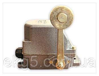
"nКорпус кінцевого вимикача КУ-701 виготовлений із матеріалу АК-12 (це дає змогу вимикачам працювати в агресивному середовищі, не відчуваючи водночас жодного дискомфорту) литтям під високим тиском у бризкозахисному виконанні. Під час встановлення на відкритому повітрі рекомендується захищати вимикачі від впливу атмосферних опадів.
\n
Призначення
/n Кінцевий вимикач КУ-701 призначений для увімкнення та вимкнення ланцюгів керування механізмів і застосовуються як бутовий. Кліматичні виконання — У, ХЛ, Т. Категорія розміщення — 2.
\n
\n
\n
\n
Пристрій і принцип дії кінцевого вимикача ку-701
\nВсередини корпусу (1) закріплений вал (8), на якому розміщені кулачкові шайби (9), храповик (11), а зовні вимикача на валу закріплюється ручка привода. Рух храповика обмежує фіксувальний механізм (5), зусилля якого контролюється пружиною (10).
\n
"nСлуговий важливий вузол вимикача КУ-701 — це блок контактів. Він складається із ізоляційної клемної колодки (6), на якій кріпляться нерухомі контакти (4), два важелі (13) з контактними містками рухомих контактів (5).
На поверхні мідних контактів нанесений шар технічного срібла, що підвищує термін експлуатації вимикача.
\n
\n[caption id="attachment_9740" align="aligncenter" width="350"]
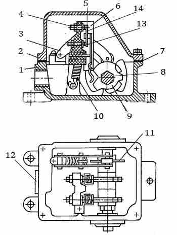
Пристрій кінцевого вимикача ку-701 [/caption]
\n
\nМеханізм вимикача захищений від впливу агресивного середовища кришкою (2) герметичне з'єднання якої з корпусом забезпечує ущільнювальна прокладка (7).
\n
\nПружини утримують контакти в замкнутому стані. У разі відхилення важеля вимикача КУ-701 від нормального положення, вал повертається й виступи на кулачкових шайбах надають тиск на виступ важіль, на якому закріплений містик рухомих контактів. Важіль повертається, відбувається розрив ланцюга головного струму або струму керування.
\n
/n Кінцеві вимикачі КУ-701 допускають
будь-який лад замикання контактів. Цей лад регулюється кулачковими шайбами положення яких на валу можна змінити.
\n
Допустимі токові навантаження
\n
\n - Струм тривалого режиму: 10А;
\n - Вмикний змінний струм (напруга до 500 В): 50 А;
\n - Вмикний постійний струм (напруга до 110, 220, 440 В): 25 А;
\n - Вимикний змінний струм (напруга до 500 В): 10 А;
\n - Вимикний постійний струм (напруга до 110, 220, 440 В): 2,0/1,5/0,5.
\n
\n
Характеристики
\n
\n
\n
\n
\n
\n
\n
\n
\n
\n
\n
\n
\n
\n
\n
\n
\n
\n
\n
\n
\n
\n
\n
\n
| Тип привода: | важіль із роликом |
| Фіксація: | самоповернення важеля |
| Кількість можливих положень важеля: | 3 |
| Кількість стійких положень важеля: | 1 (нульове) |
| Кількість електричних ланцюгів: | 2 |
\n
Тип привода кінцевих вимикачів КУ-701, КУ-703, КУ-704
\n
\n
\n
\n
\n
\n
\n
\n
\n
\n
\n
\n
\n
\n
\n
\n
\n
\n
\n
\n
\n
\n
\n
\n
\n
\n
\n
\n
| Найменування | Тип приводу | Фіксація |
| КУ-701 A | Важіль із роликом | Самоповернення важеля |
| КУ-703 А | Груз із противагою | Фіксація в крайніх положеннях |
| КУ-704 А | Важіль пластинчастий W-подібний | Фіксація в кожному положенні |
\n
Технічні характеристики
\n
Кінцеві вимикачі КУ-700 мають два незалежні електричні ланцюги та можуть працювати як на постійному, так і на змінному струмі. Допустиме струмове навантаження наведене в таблиці нижче.
\n
\n
\n
\n
\n
\n
\n
\n
\n
\n
\n
\n
\n
\n
\n
\n
\n
\n
\n
\n
\n
\n
| Сила струму тривалого режиму, А | Сила включаемого тока, А | Сила струму, що вимикається, А |
| змінна, напруга до 500 В | постійна, напруга 110, 220 440 В | змінна, напруга до 500 В | постійний
"nнапруга"
/n110, 220, 440 В |
| 10 | 50 | 25 | 10 | 2,5; 1,5; 0,5 |
\n
Пристрій і робота
"n Всі вимикачі уніфіковані та вирізняються тільки приводом. Вимикач складається з корпусу та кришки, виготовлених литими з алюмінієвого сплаву, кулачкового барабана з кулачковими шайбами та фіксувального механізму (крім вимикача КУ-703).
\n
"nВ вимикачі КУ-701 храповик під дією пружини фіксує важіль у нульовому положенні.
\n
Розміщення та монтаж
/n Кінцеві вимикачі КУ-700 можуть бути встановлені в будь-якому положенні.
"nРичаж на вимикачах КУ-700 встановлюється в різних положеннях щодо корпусу.
Для перестанови важеля на 90° за годинниковою стрілкою відносно валу зніміть важіль, поверніть його на 90° за годинниковою стрілкою, не повертаючи вала, і закріпіть на валу.
\nДля отримання потрібної схеми замикання виробляєте перебирання вимикача в такому порядку: витягніть барабан із корпусу, відверніть гайку барабана, зніміть кулачкові шайби з вала та розмістіть їх на валу згідно з обраною схемою, потім зберіть вимикач.
\n
\n Вимикачі мають бути заземлені. У вимикачах виконання Т передбачені заземлювальні болти, для виконання У — зачищена поверхня однієї з лап. Перед оглядом вимикач вимкнете від мережі.
\n
Відтворивши правильність встановлення вимикача, приводної лінійки або штиря, а також схеми, можна переходити до випробування спрацьовування вимикача за допомогою механізму.
"nПеред обробленням необхідно переконатися в надійності гальм і наявності упорів у механізмі.
"nОпробовування починайте з малих швидкостей руху приводної лінійки, поступово переходячи до повної швидкостей.
\n
Можливі несправності та методи їх усунення
\n
\n
\n
\n
\n
\n
\n
\n
\n
\n
\n
\n
\n
\n
\n
\n
\n
\n
\n
\n
\n
\n
\n
\n
\n
\n
\n
| НЕИСПРАВНОСТЬ | ПРИЧИНА | МІТОД ЗБЕРІГАННЯ |
| Надмірне підвищення температури контактів | а) слабке натискання | а) замініть пружину кулачкового елемента |
| б) нагар на поверхні контактів | б) Зачистьте контакти, що зносилися замініть |
| Не повертається важіль проводу | а) слабка пружина фіксатора | а) замініть пружину |
| б) заїдання вала в підшипниках | б) змащуйте або замініть підшипник, усуньте несоосність |
"nДоставка на склад покупця в будь-який регіон України.
\n
\nЦіна: Ціну уточнюйте
\n
\n
\n
The company sells the KU-701 limit switch at the manufacturer's price.
\nThe body of the KU-701 limit switch is made of AK-12 material (this allows the switches to operate in aggressive environments without experiencing the slightest discomfort) by high-pressure casting in a splash-proof design. When installed outdoors, it is recommended to protect the switches from atmospheric precipitation.
\n
Purpose
\nThe KU-701 limit switch is designed to turn on and off the control circuits of mechanisms and is used as a travel switch. Climatic versions — U, XL, T. Placement category — 2.
\n
Design and principle of operation of the KU-701 limit switch
\nInside the housing (1) there is a shaft (8) with cam washers (9) and a ratchet (11), and outside the switch there is a drive lever attached to the shaft. The movement of the ratchet is limited by a locking mechanism (5), the force of which is controlled by a spring (10).
\n
\nThe next important component of the KU-701 switch is the contact block. It consists of an insulating terminal block (6) to which fixed contacts (4) are attached, two levers (13) with contact bridges for movable contacts (5). A layer of technical silver is applied to the surface of the copper contacts, which increases the service life of the switch.
\n
\n
KU-701 limit switch device
\nThe switch mechanism is protected from aggressive environments by a cover (2), which is sealed to the body by a gasket (7).
\n
\nSprings hold the contacts in the closed position. When the KU-701 switch lever is deflected from its normal position, the shaft rotates and the projections on the cam washers exert pressure on the lever projection to which the movable contact bridge is attached. The lever rotates, breaking the main current or control current circuit.
\n
\nKU-701 limit switches allow any order of contact closure. This order is regulated by cam washers, the position of which on the shaft can be changed.
\n
Permissible current loads
\n
\n - Continuous current: 10A;
\n - Switchable alternating current (voltage up to 500V): 50A;
\n - Switchable direct current (voltage up to 110, 220, 440V): 25A;
\n - Switchable alternating current (voltage up to 500V): 10A;
\n - Switchable direct current (voltage up to 110, 220, 440V): 2.0/1.5/0.5.
\n
\n
\n
\n
\n
Characteristics
\n
\n
\n
\n
\n
\n
\n
\n
\n
\n
\n
\n
\n
\n
\n
\n
\n
\n
\n
\n
\n
\n
\n
\n
| Drive type: | lever with roller |
| Fixing: | self-returning lever |
| Number of possible lever positions: | 3 |
| Number of stable lever positions: | 1 (zero) |
| Number of electrical circuits: | 2 |
\n
Type of limit switch drive KU-701, KU-703, KU-704
\n
\n
\n
\n
\n
\n
\n
\n
\n
\n
\n
\n
\n
\n
\n
\n
\n
\n
\n
\n
\n
\n
\n
\n
\n
\n
\n
| Name | Drive type | Locking |
| KU-701 A | Lever with roller | Self-returning lever |
| KU-703 A | Counterweight load | Fixation in extreme positions |
| KU-704 A | W-shaped plate lever | Fixation in each position |
\n
Technical data
\n
KU-700 limit switches have two independent electrical circuits and can operate on both direct and alternating current. The permissible current load is shown in the table below.
\n
\n
\n
\n
\n
\n
\n
\n
\n
\n
\n
\n
\n
\n
\n
\n
\n
\n
\n
\n
\n
\n
| Continuous current rating, A | Inrush current rating, A | Shunt current rating, A |
| AC, voltage up to 500 V | DC, voltage 110, 220, 440V | AC, voltage up to 500 V | DC,
\nvoltage
\n110, 220, 440 V |
| 10 | 50 | 25 | 10 | 2,5; 1,5; 0,5 |
\n
\n
Design and operation
\nAll switches are standardized and differ only in their drive mechanism. The switch consists of a housing and cover made of cast aluminum alloy, a cam drum with cam washers, and a locking mechanism (except for the KU-703 switch).
\n
\nIn KU-701 switches, a ratchet spring locks the lever in the zero position.
\n
Placement and installation
\nKU-700 limit switches can be installed in any position.
\nThe lever on KU-700 switches can be installed in various positions relative to the body. To reposition the lever 90° clockwise relative to the shaft, remove the lever, turn it 90° clockwise without turning the shaft, and secure it on the shaft.
\nTo obtain the desired closing circuit, reassemble the switch in the following order: remove the drum from the housing, unscrew the drum nut, remove the cam washers from the shaft and place them on the shaft according to the selected circuit, then reassemble the switch.
\n
\nThe switches must be grounded. T-type switches are equipped with grounding bolts, while U-type switches have a stripped surface on one of the legs. Disconnect the switch from the power supply before inspection.
\n
\nAfter checking the correct installation of the switch, drive bar or pin, as well as the diagram, you can proceed to testing the switch operation using the mechanism.
\nBefore testing, make sure that the brakes are reliable and that there are stops in the mechanism.
\nStart testing at low speeds of the drive bar, gradually moving to full speeds.
\n
Possible malfunctions and methods of elimination
\n
\n
\n
\n
\n
\n
\n
\n
\n
\n
\n
\n
\n
\n
\n
\n
\n
\n
\n
\n
\n
\n
\n
\n
\n
\n
\n
| MALFUNCTION | CAUSE | METHOD OF ELIMINATION |
| Excessive temperature rise of contacts | а) weak pressure | a) replace the cam element spring |
| b) carbon deposits on the contact surfaces | b) clean the contacts, replace worn ones |
| The wire lever does not return | a) weak locking spring | a) replace the spring |
| b) shaft jamming in the bearings | b) lubricate or replace the bearing, eliminate misalignment |
\nDelivery to the buyer's warehouse in any region of Ukraine.
\n
Price: Please check the price
\n
\n


 Відправка з 18 червня 2026